Your Task
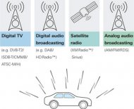
Broadcast reception in carsAutomotive multimedia – already a reality in luxury cars – is increasingly making its way into economy-class vehicles. Besides navigation systems, mobile phones and mobile Internet, also digital TV and audio broadcast receivers are included more and more often. The focus is mainly on system functions such as operation, channel search, automatic frequency change and the interaction with other devices in the vehicle's bus system. In order to test these functions, realistic receive conditions must be simulated, for example several channels that can be received in a given area. The receiver must find every channel during the search. If there are two channels with the same program on different frequencies, the receiver must first lock in on the channel with the strongest signal. If its level drops, the receiver must switch to the frequency of the other channel.
Turnkey T&M solution
Testing the channel search function requires at least two simultaneous test signals that the receiver must find. Two test signals are also needed to test the automatic frequency change. As producers for the global market, car manufacturers must offer receivers for a wide variety of standards.
If the tuners are to be tested for different TV standards in parallel and independently of one another, two test signals are needed for each of these standards. This results in a considerable number of required test signals, which are best generated using one TV signal generator each. In this case, the configuration of a signal generator exactly matches the characteristics of a TV transmitter to be simulated. As content these signal generators use transport streams that were recorded in the area to be simulated. In this way, the same receive situation (frequencies and programs) that exists on-site during a drive test is reproduced in the lab.
A combiner network combines the output signals of these signal generators and feeds them to the individual test stations via a common cable. If the test stations are far away, e.g. in a different building, an electric/optical converter at the output of the combiner network is used. An optical waveguide subsequently transmits the signal generators' sum signal virtually loss-free to the test stations, where the signal is converted back into an electric RF signal.
The signal generators are housed in a 19" rack; they are usually located in a separate, protected room and are remote-controlled from a central PC via LAN. The transport streams are on a server, from where they can be copied to the signal generators, also via LAN.
Implementation
Test setup of the turnkey T&M solution with the R&S®SFCThe R&S®SFC compact modulator is particularly well suited for these tests. Compact, cost-effective and fully remote-controllable, it supports all conventional digital and analog TV and audio broadcast standards (see table) 1). It is possible to play back customer-specific transport streams internally, as well as the entire Rohde & Schwarz library content.
In addition, the R&S®SFC features low power consumption, which considerably reduces the operating costs of the application solution. The R&S®Central TX system control software is used to control and monitor the networked devices.
1) Excluding HD Radio™ and SDARS. HD Radio™ is supported by the R&S®SFE100; the XM Radio™ and Sirius™ systems are supported by the R&S®SMBV100A and R&S®SMU200A signal generators.
https://totaltools.hr/
Source: www.rohde-schwarz.com
|
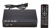
Viewtv AT-263 ATSC Digital TV Converter Box Bundle with ViewTV 25 Mile Flat HD Digital Indoor TV Antenna and HDMI Cable w/ Recording PVR Function / HDMI Out / Coaxial Out / Composite Out / USB Input CE (ViewTV)
|
|
|
Infitary Digital ATSC HD TV Receiver Converter Tuner Box for Analog TV with Recording PVR Function HDMI YPbPr RCA Coaxial Composite Output / USB Input USA Home Theater (Infitary)
|
Related posts:
